


This tutorial will walk you through setting up a string of colorful holiday lights that connect to the internet. The lights can display many types of animations and colors based on information sent to it using Adafruit’s IO service. Once connected and programmed, IFTTT can be used to set date triggers as well as change animations based on your GPS location, the weather report for the day, and even when you are getting a call from your mother.
The hard stuff is already done and with just a bit of soldering and a few code edits, you will be deep into the beast known as the Internet of Things.
What You Will Need
This is a list of parts that you will need to make this project.
1 x NodeMCU
1 x 5 Volt MicroUSB power supply
Other than these you will need a computer.
A WiFi connection to the Internet.
One Micro USB cable for programming the NodeMCU.
The Arduino IDE with ESP8266 support.
Connecting the Wires
This is actually a simple circuit to wire because WS2812 LEDs only need 3 wires to connect. So we need to connect Power, Ground, and Signal to the NodeMCU Pins.
WS2812 LEDs typically work with 5 volts of power, but they can still work with 3.3 volts. That is ideal because the ESP8266 can not handle anything over 3.3 volts.
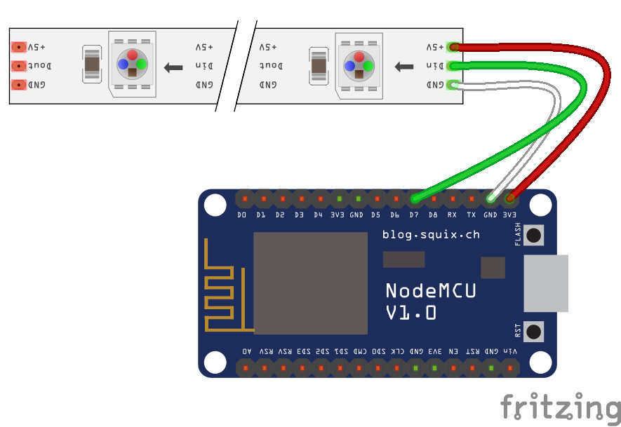
When you are connecting the WS2812 LEDs, be sure that you are connecting them in the right direction. Most of these LED strings and strips have a small arrow on them that should be pointing away from the connection to the NodeMCU. This is the side that you want to connect the LEDs to.
The LED string that I recommend comes with a connector that can be soldered to the NodeMCU so that you can swap about projects easily.
- The Red wire gets attached to one of the 3V3 pins on the NodeMCU.
- Connect the White wire to one of the GND pins.
- Pin D7 should be connected to the Green wire.
Adding the Libraries
We will need to Install a few Libraries into the Arduino IDE before we can get going on the code.
- From the Arduino IDE, got to the Sketch menu.
- Select Include Library and click Manage Libraries…
- Type the library name into the Filter your search field.
- When you see the library that you want, click it and press the Install button.
There are four libraries that are needed for this project.*
- Adafruit IO Arduino
- Arduino MQTT Library
- ArduinoHttpClient
- FastLED
Install all four of these and we should be ready to do some coding.
Next you want to download the code for this project.
Unzip the Adafruit-IOT-master.zip file and copy the IOT_Holiday_lights into your computers Arduino folder.
Now you will want to open the IOT_Holiday_lights.ino file.
This file should include the config.h file as an extra tab near the top of the code window.
We actually don’t need to do much of anything with the main code, that part is pretty set. We will need to make some changes to the config.h file though, so lets click that.
There are four pieces of information that we need to give our code so that it can connect to the internet and start receiving commands.
- Adafruit User name
- Adafruit WiFi Key
- Your WiFi SSID
- Your WiFi Password
Setting Up AIO
This is a good time to get our Adafruit IO account set up. If you already have an account set up with Adafruit, log into the site now. If not, you will need to set on up.
- Go to www.adafruit.com
- Click the Sign In link.
- Click the SIGN UP button.
- Enter your information and click CREATE ACCOUNT.
Now that we are logged in you want to go to io.adafruit.com. This is Adafruit’s free IOT server that will let you easily, and securely connect devices to IFTTT and provide control access form anywhere you have internet access.
Click the link for View AIO Key.
This will give you the Adafruit Username and Active Key. Both of these need to be copied and added to the config.h file as the Adafruit User name and Adafruit WiFi Key.
 #define IO_USERNAME "Adafruit User name"
 #define IO_KEY "Adafruit WiFi Key"
The user name will not change unless you want to use another account. The Key is your security token and this number is randomly generated to encrypt your data. Your Key will not change unless you press the Regenerate AIO Key button. You only really need to regenerate your Key if someone hacks your account or you accidentally post your key to a public website. Your Key gives anyone access to your feed data including the ability to send commands to your stuff. So keep it secret and safe.
Adding Feeds to AIO
For this project we are using a communication called MQTT. This is a very low bandwidth IOT service that uses SSH to send and receive messages to and from connected devices very quickly. For this project, Adafruit IO is used as the MQTT Broker. That basically means that all data passes through Adafruit IO and it sends information back out to whatever devices want access to that information. Out holiday lights will be set up as an MQTT Client and will be keeping track of information stored on the Broker in the form of a Feed. Now we will create those Feeds on Adafruit IO to make it easy for us to interact with them.
- On the left side of the Adafruit IO site, click on the Feeds link.
- Click the Actions menu, then select Create a new Feed.
- Enter the Feed Name.
- You can enter a Description, but it is not needed.
- Click the Create button when finished.
You will want to create three Feeds named setpower, setcolor, and seteffect. These Feeds are also referenced in the Arduino code that we should already have open. Look at the IOT_Holiday_lights.ino tab and near the top you should see the following:
 /************************ AIO MQTT feeds *******************************/
 AdafruitIO_Feed *setpower = io.feed("setpower");
 AdafruitIO_Feed *setcolor = io.feed("setcolor");
 AdafruitIO_Feed *seteffect = io.feed("seteffect");
The way this brakes down is that the first part sets a local variable that the NodeMCU uses in its code to trigger actions that actually control the LEDs.
For the first entry we have a local string variable set to setpower. This is global so we can recall the value of setpower from anywhere in our code.
AdafruitIO_Feed *setpower = io.feed(“setpower”);
We then connect the value of setpower to the incoming MQTT feed from Adafruit IO named setpower. Each MQTT packet that the NodeMCU receives from Adafruit IO will contain the Feed name and the data sent.
AdafruitIO_Feed *setpower = io.feed(“setpower“);
So if you want to add another feed to your device, just be sure that you use the same naming conventions. If you want to change the name of your feed, it is best to do a Find and Replace for the Feed name and local variables.
Adding WiFi Credentials.
The last part to our code is adding our WiFi SSID and Password. This will let the NodeMCU connect to Adafruit IO over the internet.
- In the config.h file, look for the section labeled WiFi.
- Replace the part that says Your WiFi with the SSID for your WiFi network.
- Change the WiFi Password text to the password that you normally use to connect to your WiFi. Remember that this is case sensitive.
The SSID is the name of your WiFi connection. It should be the same as what you see in that list you use to select your network from your computer or phone.
Note: The ESP8266 chip used by the NodeMCU will not connect to a 5 GHz WiFi connection.
Upload the Code
Now lets upload the code to the NodeMCU.
- First, go to the Tools menu.
- Select Board: … and click on NodeMCU 1.0 (ESP-12E Module)
- Connect your NodeMCU microcontroller to the computer using a micro USB cable.
- Go back to the Tools menu.
- Select Port and click on the new COM port that appears.
- With the IOT_Holiday_lights.ino open, click the Upload button.
- After a few seconds you should see the blue LED on the NodeMCU blink very fast. This means that it is uploading the code. You should also see a bunch of orange dots filling up the bottom panel of your Sketch window.
- If all was successful, you should see the Done uploading message near the bottom of your code window.
Now we can check to see if everything connected by clicking the Serial Monitor.
- Once open, you should see something saying Connecting to Adafruit….
- Eventually it should switch to Connect.
- Go back to your Adafruit IO page.
- Click on the Feeds link.
- Click the setpower Feed.
- Click the Actions menu at the bottom of the data display.
- Select and click Add Data.
- Enter the word ON into the VALUE field.
- Click the Create button.
Now you should see the new data in your Adafruit IO window.
If you go back to the serial monitor window, you should also see the new message with the same data.
If all of that works, we should be in business.
Try it out!
Now connect the WS2812 LEDs to the NodeMCU if they were not already.
Send commands to the new Holiday lights the same way that we did for the test. Your light string will only do something if you use the right commands so here is a list of what you will want to send each Feed.
setpower
- OFF
- ON
setcolor
This will accept any Hex color value (#a50e0e)
seteffect
- BPM
- Candy Cane
- Confetti
- Cyclon Rainbow
- Dots
- Fire
- Glitter
- Juggle
- Lightning
- Noise
- Police All
- Police One
- Rainbow with Glitter
- Rainbow
- Ripple
- Sinelon
- Twinkle
Next Steps
Now that you are connected, you can create a custom Dashboard with buttons to control your lights. You and also download an MQTT client app and connect it to your Adafruit IO account.
Adafruit IO is also connected to FITTT as well. Using that, you can connect your lights to Email, Twitter, Weather Underground, and even your cellphones GPS.
The sky is the limit, so go forth and enjoy your new IOT Holiday Lights.
*The library versions used at the time of publication are as follows:
- Adafruit IO Arduino V2.6.0
- Arduino MQTT Library V0.17.0
- ArduinoHttpClient V0.3.1
- FastLED V3.1.6