


Overview
Prototyping a circuit board in this way is a good idea so you can be sure that things are working before sending your PCB off to a fabricator. This method is also a good way to do low run or one off testing PCBs.
G-Code is made up of some simple commands that tell a CNC mill how to move so that your designs come out correctly. This is also called a Tool Path. PCB-GCode is an add-on for EAGLE that lets you create a Tool Path in G-Code so that it can be made by a CNC Mill like my Shapeoko 2. Though there are many ways to create G-Code for PCBs, I will focus on EAGLE and PCB-GCode because they are rather easy to use and the software is free for making basic PCBs
Software Used:
EAGLE is free to use for making small PCBs. We will assume that you already have EAGLE installed and that you know how to use it for creating a PCB design. If this is not the case, I recommend checking out any one of the many tutorials that people have made for EAGLE like this one.
Adding PCB-GCode to EAGLE
Once EAGLE is installed, PCB-GCode will have to be added to the User Language Programs list so it can be used.
Note: These instructions are for EAGLE 7.2.0 running in Windows 7, but they should work for other configurations as well.
- Open EAGLE.
- From the Control Panel window, click Options.
- Under Options, click Directories.
- Add ;$HOME\eagle\external_usr-lang-prog\pcbgcode to the end of what is already in the User Language Programs field. Note: Do not delete any other text unless you know what you are doing or you will loose access to other resources and libraries in EAGLE.
- Click on the OK button.
- Now click Yes to let the program create a new folder for this directory.
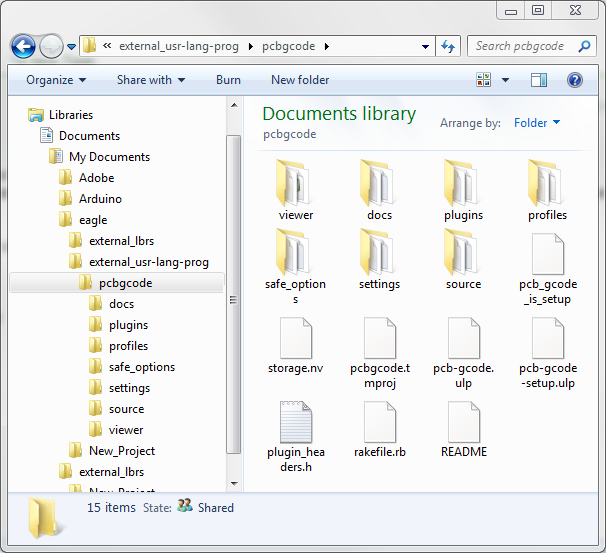
- Close EAGLE and open the Documents folder on your computer.
- Open the eagle folder.
- Open the external_usr-lang-prog folder.
- Now place all of the files from the PCB-GCode Zip file into the pcbgcode folder. (See Figure 1)
Setup PCB-GCode
Now that PCB-GCode is installed, we need to set up a few things so that it can easily generate G-Code that works with your CNC Mill. The settings I will be recommending are what I found to be the best for the Shapeoko 2, but they should work with any other CNC Mill that uses generic G-Code.
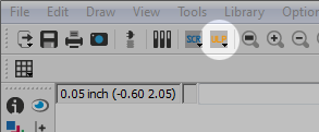
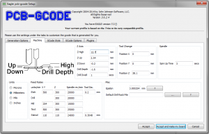
- Open your EAGLE file, then click the ULP icon. (See Figure 2)
- Navigate to the pcbgcode folder located in Documents\eagle\external_usr-lang-prog\.
- select the pcb-gcode-setup.ulp file and click Open.
- The first time pcb-gcode-setup.ulp is opened, you will be asked to select a default G-Code profile.
-
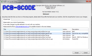
Figure 3 I selected generic.pp for my CNC Mill. (See Figure 3)
- Click Accept when done.

PCB-GCode is now ready to be used for generating G-code from your design.
Adjusting the Settings
The default settings the PCB-GCode uses may work for many CNC Mills, but I think they are set a little high and I did not have much luck with them. Lowering the feed rate reduces the stress on the carbide milling bits so that they stay sharp and it will make very clean edges around your traces. We also just want to take off the copper layer without going too deep into the broad. Here are the settings I have found to work the best with my Shapeoko 2 using a carbide engraving bit, drills, and a 0.0625 inch end mill.
Generation Options
These are basic settings for what types of Tool Paths you want to create and how detailed they should be.
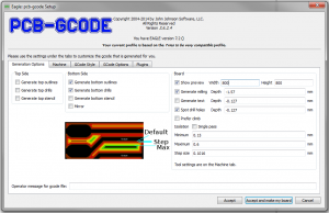 The Top Side and Bottom Side setting will depend on whether you will be making a single or double sided PCB. We will get more into that later.
- Show preview is always good to have checked so you can see that everything turned out how you expected it to. I like to keep the Width and Height of the preview window at 800 x 600.
- Generate milling is used for cutting the PCB outline. The one issue that I have with this option is that it cuts all the way through the carrier board using just one pass. This puts a huge amount of stress on the end mill resulting in jagged edges, misalignment, and broken bits unless you go really slow. If you have any other way to cut out the final PCB, I would go with that. I will have more info on other options later in the tutorial. When I do use this option, I set a depth of -0.064 inches or about 0.002 in over the measured thickness of my carrier board. Alternately, you can use this option to draw symbols in the PCB by setting the depth to -0.005 inches.
- Generate text is used to engrave text onto your PCB. Only text that uses the Vector font and is on Layer 46 Milling will be included in the G-Code. I have this option checked and set to a depth of -0.005 inches.
- Spot drill holes will make small marks wherever a hole will be drilled after the trace isolation cuts are made. This helps the drill bits get nice and centered when drilling the holes. Do not set the depth for this very high or you will damage your bits. I have this option checked and set to a depth of -0.015 inches.
- Prefer climb setts the overall direction that the CNC Mill should move in for milling. I do prefer to have my mill do climbing cuts and that is why I have this option checked.
- Isolation lets you control how the software will outline each of your traces. These settings depend heavily on the tip diameter of the end mill or engraving bit that will be used to outline your traces. We will talk more about this later on.
This is what a isolation cut loos like using an End Mill vs an Engraving Bit. - Single pass only dose one outline around your traces. This potion should only be used if you are using a larger diameter end mill or if you are really good at soldering components without getting solder everywhere.
- Minimum lets you set the smallest amount of space that your end mill or engraving bit can cut. I have this set to 0 inches to ensure that every trace is outlined at least once to isolate it.
- Maximum sets the maximum spacing that you want cut around each trace. This will determine how many times the CNC mill will outline each trace. I set this option to 0.015 inches to give me just enough room to easily solder things.
- Step size tells the software how much space your want between isolation passes. If you are using an end mill, this should be about 40% of the tip diameter of your bit. 0.004 in. Engraving bits can use a step size equal to the flat diameter of the bit because it is tapered and that makes the cuts wider as it goes deeper into the carrier board.
Machine
These settings control how fast the CNC Mill will cut, details about your cutting tools, and the units of measurement you wish to use.
- Z Axis lets you set some standardized milling depths.
- Z High sets the safe height for the mill to move around without running into anything like your clamps. 0.5 inches is a safe bet for this.
- Z Up is the safe height for movements from one cut to the next. I set this to 0.1 inches.
- Z Down sets the cutting depth for the trace isolation. This should be set to go just bellow the copper layer. I use -0.007 inches.
- Drill Depth should be set to about 0.005 inches below the thickness of your carrier board. So if your carrier board is 0.062 inches, you would set this option to -0.067 inches.
- Drill Dwell tells the machine how long it should wait before pulling the drill bit back out of a newly drilled hole. About 1 second is good to get a cleanly drilled hole.
- The Tool Change options don’t work so well, but I put 0 in for Position X and Y and 1 inch for Position Z.
- Spindle is used to set the time it takes for the spindle to get to full speed once it is turned on. If your CNC Mill dose not automatically turn your spindle or router on and off, don’t worry about this setting.
- Units tells the software what unit of measurement you want to use for everything. I left it on Inches, but you can use whatever you like best so long as you remember the difference between 0.5 Inches and 0.5 Millimeters.
- Feed Rates lets you set the optimal speed that your CNC Mill will move while cutting and drilling. This is very important to prevent your bits from braking and getting clean cuts. I have found that it is better to start these settings low if you are not sure what works best, then increase the speed if necessary. The Shapeoko 2 does not handle the stress of high feed rates that well so the following settings should work for any other CNC mill.
- Etch settings are used for the trace isolation outlines.
- X Y: 20 in/min
- Z: 10 in/min
- Spindle rev/min: 30000
- Tool Dia.: 0.007 in
- Drill sets the drilling speed.
- Z: 20 in/min
- Spindle rev/min: 30000
- Mill settings are used for cutting out the PCB when finished. You may remember that I do not recommend using the Milling option unless you have no other way to cut your final PCB down to size. If you need to use this option, go very slow because it will put a lot of stress on your end mill.
- X Y: 2 in/min (Yes, that is 2 inches per minute and that is still fast for my preference.)
- Z: 5 in/min
- Spindle rev/min: 30000
- Text is basically the same as Etch, so I use the same settings.
- X Y: 20 in/min
- Z: 10 in/min
- Spindle rev/min: 30000
- Stencil settings can be used to cut out thinner sheets of plastic to use as a mask for solder paste. Though I have not used it, this would probably work well with the same settings as Etch.
- X Y: 20 in/min
- Z: 10 in/min
- Spindle rev/min: 30000
- Tool Dia.: 0.007 in
- Click on the ? buttons if you really want to know what the Misc options are, but the are not important for what we are doing.
- Etch settings are used for the trace isolation outlines.
GCode Options
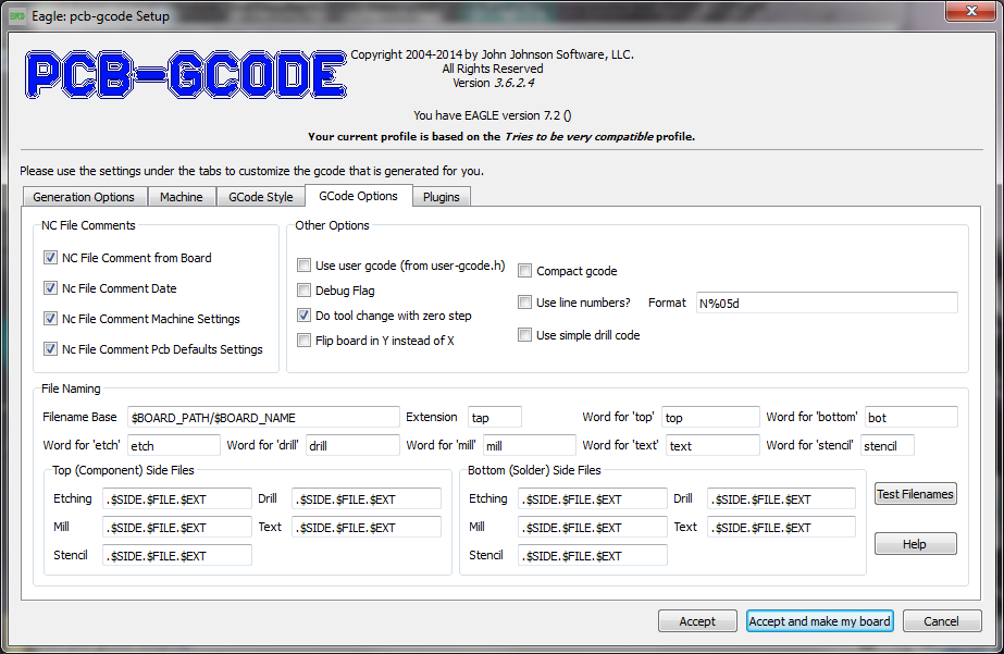
I have found that PCB-GCode puts some rather long notes into the G-Code that it generates. This results in errors whenever I try and send the G-Code file to my CNC Mill. Un-checking all of the NC File Comments options will fix this issue.
Unfortunately, the G-Code file for drilling still gives me an error due to a long notation at the top of the file. This is easy to fix and we will go over that in the Troubleshooting section.
Under Other Options, I only check the Do tool change with zero step and Use simple drill code options. The Format should be set to N%05d by default.
File Naming can be changed if you really want to, but I would just leave it alone.
Prepping Your EAGLE File
Wire Placement
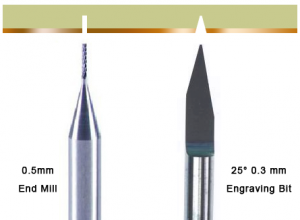
The spacing between your wires and pads are dependent on how small of a milling bit you are using. If you are using an end mill with a 0.8 mm diameter tip, then all of your wires and pads should have at least 0.8 mm of spacing between them. This gets a little tricky when you are dealing with an engraving bit, because the cut widens as it goes deeper, but I would not worry about it unless you need a fine pitch. I tend to go with a 20° engraving bit with a 0.2 mm tip. Soon I will try to do a 0.4 mm pitch using a 10° engraving bit with a 0.1 mm tip and I will update this tutorial on how that goes.
To ensure that I get everything spaced correctly, I use the Design Rule Check (DRC) to let me know if my traces are to close.
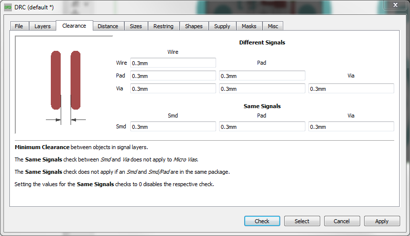
- Open your EAGLE file, then click the
 DRC icon.
 - Click the Clearance tab.
- To ensure that all of your traces get isolated, change all of the values to the diameter of your milling bit. For example; I use an engraving bit that cuts at about 0.3 mm and that means I will change all values to 0.3 mm. (See Figure 4)
- Now click the Apply button.
- Click the Check button to look of DRC errors.
- If you have any errors, they will show in the DRC window.
- Double click an error from the list to show you where it occurs in your design.
- Fix or Approve your errors before running PCB-GCode to create the tool paths.
G-Code for Single Sided PCBs
Top side or Bottom
There are two ways that you can design your PCB for a single sided board. You can design your traces from the top or from the bottom. Most of this depends on how you want to mount your components. Through-hole components are easier to solder on if you put them on the non copper side so that the pins stick out through the copper. Service mounted components can only be placed on the copper side.
This is where you may have to think a bit about your design. but no matter what you do, always keep your wires set to all Top or all Bottom. Components that use the green drilled Pads or Vias will automatically trace on the Top and Bottom of the PCBs.
So if you are using through-hole components, you may want to do all of your wire connections using Bottom wires. Also be sure that you mirror any text that you want etched as well so that is shows up in the right place.
Creating the G-Code
Now we are ready to create the G-Code for this PCB.
- First, click the
 ULP icon at the top of your EAGLE file.
 - Navigate to the pcbgcode folder located in Documents\eagle\external_usr-lang-prog\.
- select the pcb-gcode-setup.ulp file and click Open.
- Check-mark Generate Outlines and Generate drills for the Top or Bottom side depending on how your PCB was designed.
- Don’t forget to check-mark the Generate milling, Generate text, and Spot drill holes if those options are used in your design.
- When done, click Accept and make my board.
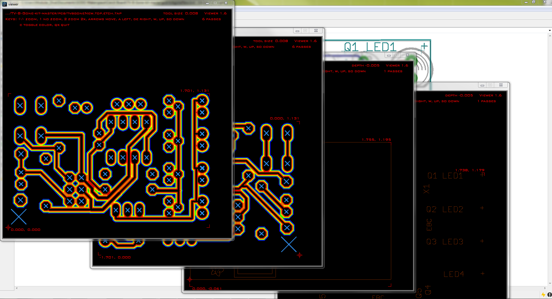
- A preview of the trace outline will display.
- Type the letter C to see the outlines more clearly.
- Inspect the preview to be sure that everything looks good.
Note: if there are gaps between your outlines, try adding a box to define the outside edges of your PDB. - Type the letter Q to close the window.
- Click the OK button on the popup window to see the next preview.
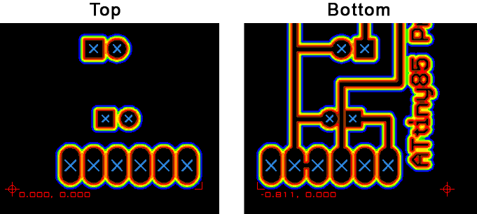
Generate Outlines and Generate drills show up on the same preview. Other options like Generate milling and Generate text will display a preview for the top, then one for the bottom. The G-Code files are saved to the same location as your EAGLE file.
Know your starting point
The key difference between doing a Top or Bottom PCB is the point of origin. This is the point where the CNC Mill will start at. The point of origin is represented by a small + made of dotted lines. Most programs use a point of origin that is in the bottom left corner. This works out perfect if you designed your PCB with all Top wires. However, the point of origin is moved to the bottom right corner if your PCB was designed with Bottom wires.
The simple way to deal with this change in the point of origin is to start the Bottom wire PCB in the lower right corner of your CNC Mills work aria. Though this will work, if you really need to start in the lower left, there is a way to know how far over you will need to move for the new point of origin.
If you have Show preview enabled in the Generation Options of PCB-GCode, you will notice something that looks like a red + with a circle on it. This is known as a registration mark. The registration mark shows you where the point of origin is and the two sets of red numbers tells you the exact distance that mark is from point 0.000, 0.000. You may notice that in figure 5, the registration marks are on opposite sides and the numbers are not the same.
So if I were to start our CNC Mill at the bottom left corner, or X 0.000 and Y 0.000, I would use the CNC software to move the X axis to 0.811. One I am there, you can reset that new position as X 0.000 and Y 0.000 by using the Reset Zero button from your CNC Mill software.
We will go over this again in a tutorial about setting your CNC Mill up and running the code.
As for the cutting your PCB free of the larger board, I would create that tool path with a program like VCarve or free software like Easel. Just be sure that everything lines up with your point of origin from your EAGLE file.
G-Code for Double Sided PCBs
Two sided PCBs work out the same way as the single sided boards except that the registration mark is more important so that the top milling lines up perfectly with the bottom. You will want to run all of the G-Code for the Top first, then flip the PCB over to run all of the Bottom G-Code. For this type of board, I would recommend adding a set of holes that can be used to align the board properly when it is turned over. Just be sure that the holes you drill will be in the same place even when the PCB is flipped. I suggest placing these holes on all 4 corners of the PCB.
We will get into more about lining up your PCB in a tutorial about setting your CNC Mill up and running the code.
Troubleshooting G-Code Errors
The most common error that you will encounter has to do with long comments that appear at the beginning of the Drill files.
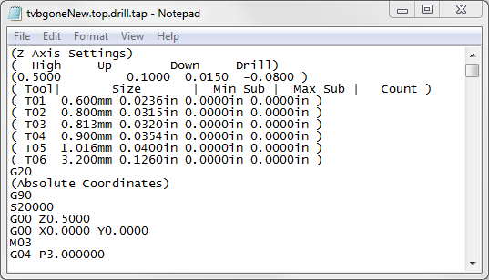 This error is easy to fix with the help of a text editor.
- Locate and open the (your file name).top.drill.tap file using a text editor.
- The comments are enclosed with parentheses ().
- You can remove all of the comments from this file, but the long comment on line 4 is the most likely one to give you trouble.
- Save and close the file.
- Now open (your file name).bot.drill.tap and repeat the process.
All of the other files will run smoothly. However I would suggest, if you understand G-Code, that the following code be added just after the last Z movement.
G00 Z1.0000
G00 X0.0000 Y0.0000
This will bring the CNC Mill back to your 0, 0 position so you are ready to load the next G-Code file.
You can also add G21 to the very end to switch back from Inches to MM (the software default)
For more about G-Code, have a look at these resources:
Many Thanks Richard for sharing this! a big help
sir you know about hardwaRE FOR CNC
hi richard, i was try this tutorial but i get a wrong scale on my PCB when thats don milling my PCB, what can i do for this issues? thanks
I would check to make sure that you are using the corect unit of measurement. Some CNCs start using mm and some start with inches. You can use G20 and G21 to switch your CNC software to the correct unit of measurement. Google G-code and you will get a full list of what code dose what including G20 and G21.
Hi Sir,
Many thanks for all your information. I bought my first DIY CNC last week. It’s also my first time creating PCB and I choose Eagle to do it. After reading all your information about PCB G-Code I made my first PCB (Single Side).
Question
I know that you don’t like using the milling option to cut your PCB but I want to do it so I checked the milling option.
The problem is that the file that end with “top.mil.tap” or even “bot.mil.tap” doesn’t contains the draw to cut the pcb.
When I import them into GBRL software, the preview is empty.
The text is also empty
What do I need to do in Eagle so PCB-G-Code will b able to generate what it takes to cut my pcb ?
ViewNote
I’m using Eagle 8.6.3 (Free) and PCB-Gcode 3.6.2.4. When I say make my board I get the first preview but all other preview generates an error.
“Can’t open \path to the folder with Gcode3.6.2.4\viewer\application.windows\data\optimize_me.txt” Permission denied
The folder for PCB_GCode was in my Eagle folder on my drive C at first. I tried to change for another location but it does the same. I change the location in the Eagle control panel option for directory.
Thanks
I have not tried this with Eagle 8+ yet, but you do have to set a Milling path. I have had issues when using Arcs in my Milling layer, so try just doing a simple box first.
The issue I have run into is not having a way to set multiple passes for the milling cut. I was just exporting a DXF of my PCB and importing that to a CNC tool path creator like Aspire. Now I just open and edit the Gcode to split the single cut into multiple ones. That can be a bit tricky to do unless you are somewhat familiar with Gcode though.
Hope that helps 🙂